Datasheet
Modules Overview
The SNAP Engine Model SM220 series consists of the SM220UF1 part number. It is an IEEE 802.15.4, low-power, highly reliable solution for embedded wireless control and monitoring networks requiring high data rates. It embeds Synapse’s SNAP OS, the industry’s first Internet-enabled, wireless mesh network operating system, into the Atmel ATmega128RFA1 single-chip AVR® microcontroller with an integrated transceiver that delivers up to 2Mbits/sec. This low-cost module can have current consumption under 390nA to better enable battery-driven systems. The SM220 also includes a Skyworks SE2431L front-end module, which provides a power amplifier and LNA for increased range.
SNAP’s on-board Python interpreter provides rapid application development and over-the-air programming, while Atmel’s low-power RF single-chip design saves board space and lowers power consumption. The modules provide up to 15 channels of operation in the ISM 2.4GHz frequency band.
By default, the SNAP operating system automatically forms a mesh network with other nodes immediately on receiving power. No further configuration is necessary. Multiple unrelated SNAP networks can exist within the same area through several configuration options outlined in the SNAP User Guide available from www.synapsewireless.com
Note
Channel 15 is receive-only due to FCC power restrictions
Datasheet covers Part Number SM220UF1:
32 GPIO with up to 7 A/D inputs
128k flash, 58.5k free for over-the-air uploaded user apps
Two UART ports for control or transparent data
- Low power modes:
Timed Sleep Mode 1 : 1.27 µA
Timed Sleep Mode 2 : 1.47 µA
Untimed Sleep Mode : < 390 nA
Spread Spectrum (DSSS) technology
Up to 2 Mbps radio data rate
2.4 GHz RF Frequency
AES 128-bit encryption
Integrated on-board compact F antenna or U.FL connecter
Surface Mount, Solder-able
4K internal EEPROM
8 PWM outputs
Supports over the air firmware upgrades.
Specifications
SM220 Specifications at 25° C and 3.3V unless otherwise noted
Performance |
Outdoor LOS Range |
1 mile using u.fl antenna |
Transmit Power Output |
up to +20 dBm |
|
RF Data Rate |
250Kbps, 500Kbps, 1Mbps, 2Mbps |
|
Receiver Sensitivity |
-103 dBm (1% PER, 250Kbps) |
|
Power Requirements |
Supply Voltage |
2.0 - 3.6 V |
Transmit Current (Typ@3.3V) |
at +20 dBm: 150 mA
at +6 dBm: 55mA
|
|
Idle/Receive On (Typ@3.3V) |
22 mA |
|
Idle/Receive Off (Typ@3.3V) |
7.8 mA |
|
Sleep Mode Current (Typ@3.3V) |
Timed Sleep: 1.27 µA Untimed Sleep: 390 nA |
|
General |
Frequency |
ISM 2.4 GHz |
Spreading Method |
Direct Sequence (DSSS) |
|
Modulation |
O-QPSK |
|
Dimensions |
29.8mm x 19mm |
|
Operating Temperature |
-40 to 85 deg C. |
|
Antenna Options |
U.FL and on-board compact F antenna |
|
Weight |
3 grams |
|
Networking |
Topology |
SNAP |
Error Handling |
Retries and acknowledgement |
|
Number of Channels |
15 fully operational channels. 1 receive only. |
|
Available I/O |
UARTS with HW Flow Control |
2 Ports |
GPIO |
32 total; 7 can be analog-in with 10bit ADC |
|
Agency Approvals |
FCC Part 15.247 |
FCC ID: U9O-SM220 |
Industry Canada (IC) |
IC: 7084A-SM220 |
|
You must preserve access to UART1 as a serial connection in order to be able to update firmware on the node, or to recover the node by forced script removal or parameter reset.
Electrical Characteristics
SM220 DC Characteristics at 25° C
Symbol |
Parameter |
Condition |
Min |
Typ |
Max |
Units |
VCC1 |
Supply Voltage |
2.0 |
3.3 |
3.6 |
V |
1Absolute maximum stress rated voltage for VCC is -0.3 to 3.6. It is recommended that bulk capacitance be located as close as possible to the VCC pin on the host board. Ideally, use a single 47µF capacitor at 10V directly at the VCC pin.
ADC Electrical Characteristics (Operating)
VREFH1 |
ADC Voltage Reference, High |
Programmable |
1.5 |
1.6 |
1.8 |
V |
VINDC |
Analog input voltage |
Single Ended |
0 |
1.8 |
V |
|
Differential2 |
0 |
3.3 |
V |
1VREFH is programmable to three fixed values; 1.5V, 1.6V, and 1.8V. The VREFHvalue will be 1.6 volts if you do not explicitly adjust it by poking the ATmega128RFA1 registers.
Mechanical Drawings
The drawings below show the modules with the compact F antenna and U.FL Connector options.
Note
The area under and around the module’s antenna (marked KEEP OUT AREA and tinted red) should have no components and no copper on any layer of the printed circuit board. Additionally, leave enough clearance around the module for worst case component and processing variances.
For best performance, the module should be mounted on the outside edge of the circuit board with the antenna side as close to the edge of the board as possible.
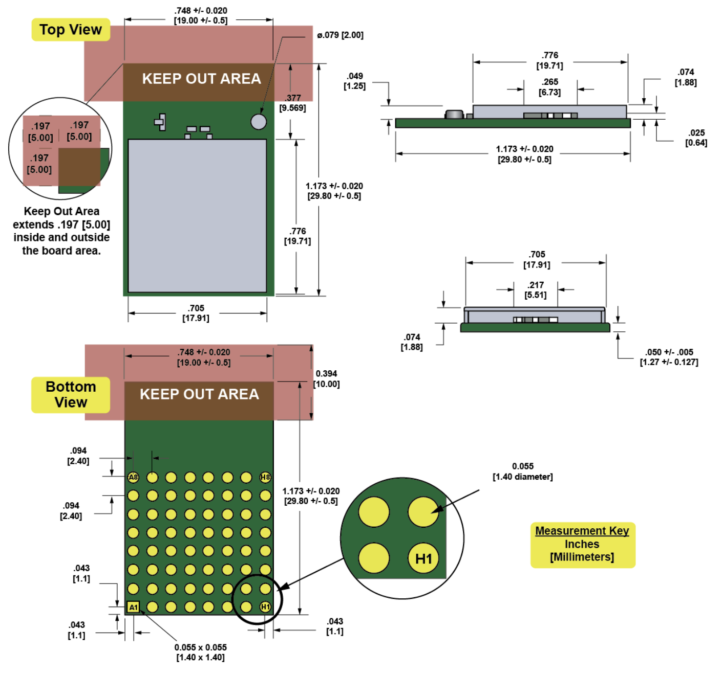
SM220UF1 Mechanical Drawing
Note
Metric measurements in millimeters are between brackets, with standard measurements in inches below.
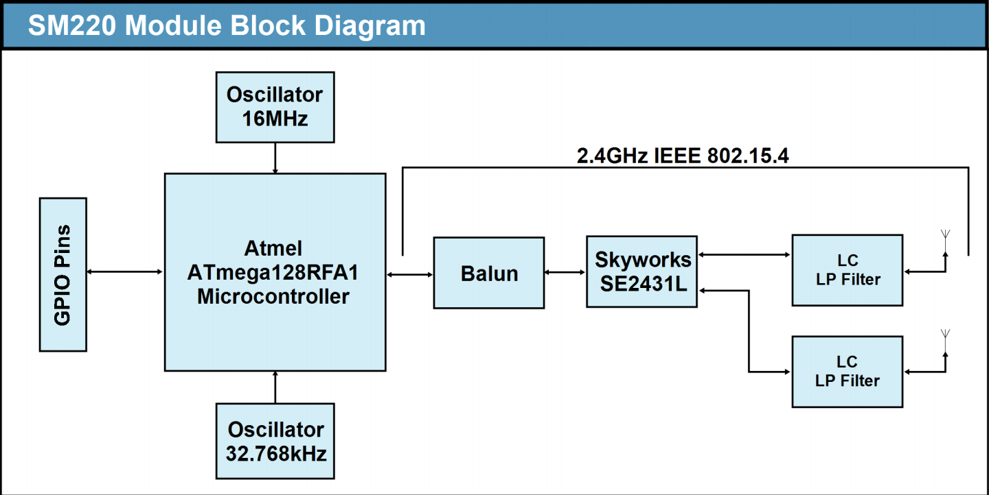
Block diagram showing the major subsystems comprising Model SM220
Antenna Gain Performance
Note
Antenna gain performance information is based on information from the individual companies at the time this document’s release. For added assurance, it’s best to obtain antenna performance information directly from that antenna’s manufacturer.
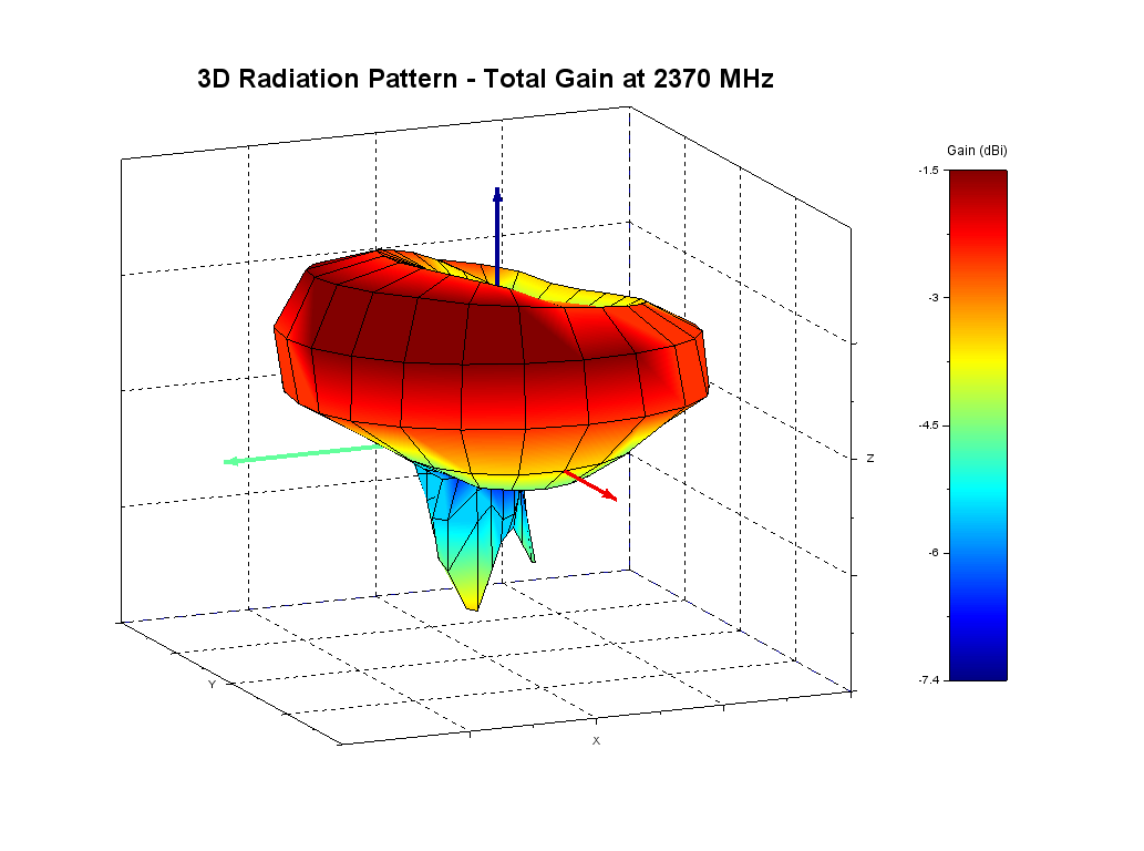
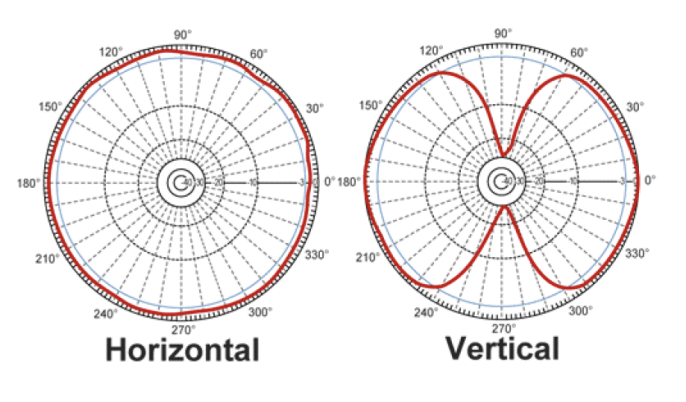
Compact Internal F Antenna Gain Performance at 2370 MHz
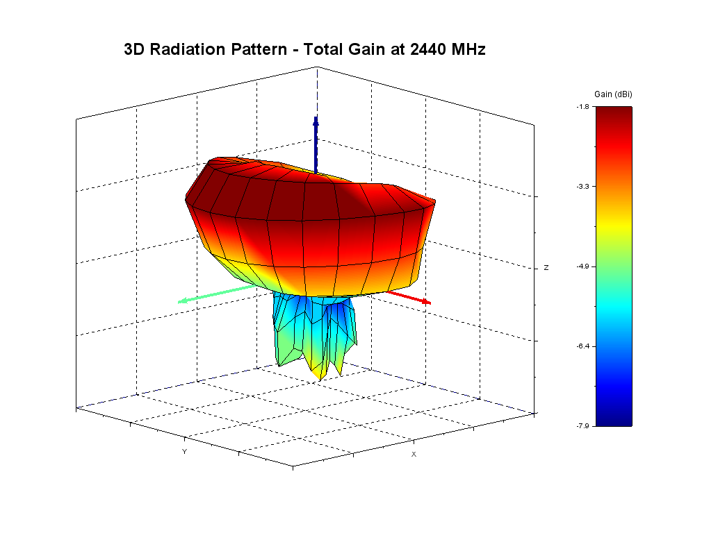
Compact Internal F Antenna Gain Performance at 2440 MHz
HyperLink Technologies HG2405RD-RSP Antenna Gain Performance
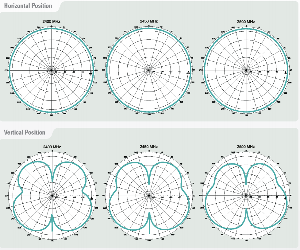
Pulse W1027 Antenna Gain Performance
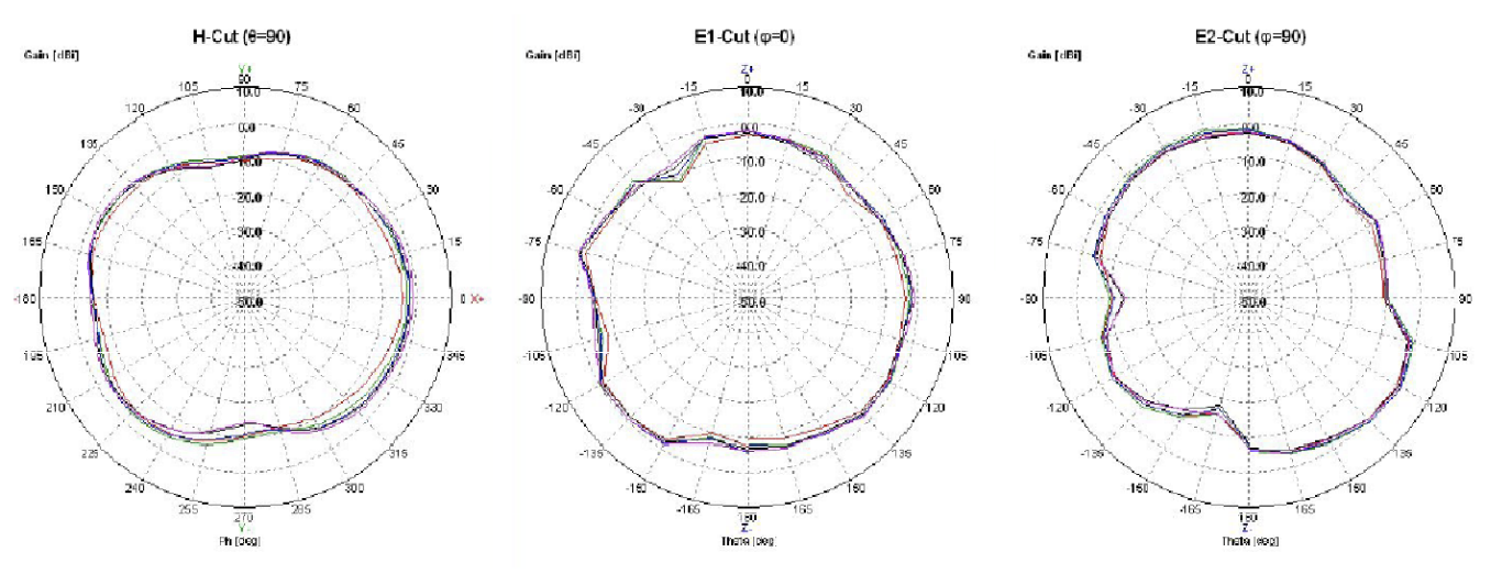
ANT-2.4-CW-RAH-RPS Antenna Gain Performance
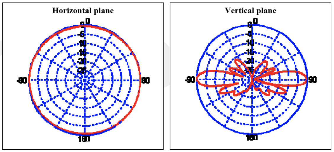
ANT-OSC-8.0-1 Antenna Gain Performance
Board Mounting Considerations
Processing
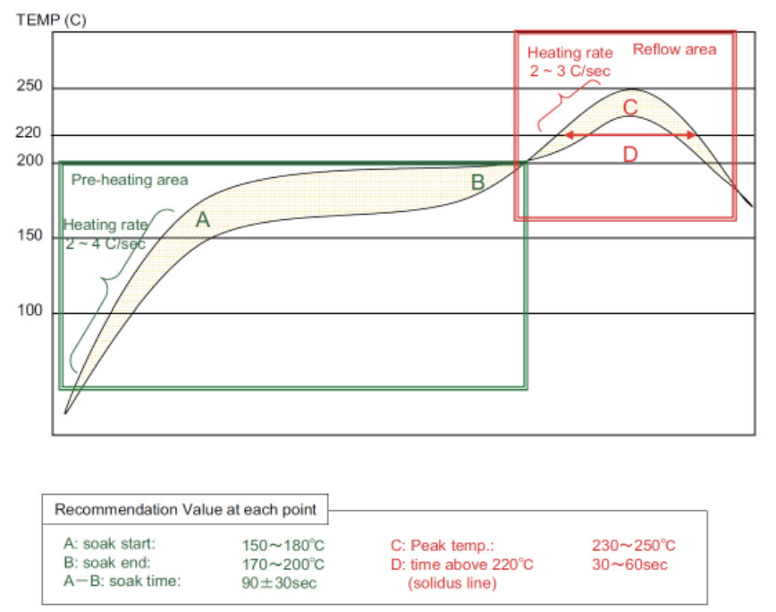
Recommended Reflow Profile
Parameter |
Value |
|---|---|
Ramp up rate (from Tsoakmax to Tpeak) |
3°/sec max |
Minimum Soak Temperature |
150°C |
Maximum Soak Temperature |
200°C |
Soak Time |
60-120 sec |
TLiquidus |
217°C |
Time above TL |
30-60 sec (recommended: 40 sec) |
Tpeak |
230° - 250°C (recommended: 235oC) |
Time within 5° of Tpeak |
20-30 sec |
Time from 25° to Tpeak |
8 min max |
Ramp down rate |
6°C/sec max |
Pb-Free Soldering Paste
Use of “No Clean” soldering paste is strongly recommended, as it does not require cleaning after the soldering process.
Cleaning
In general, cleaning the populated modules is strongly discouraged. Residuals under the module cannot be easily removed with any cleaning process.
Cleaning with water can lead to capillary effects where water is absorbed into the gap between the host board and the module. The combination of soldering flux residuals and encapsulated water could lead to short circuits between neighboring pads. Water could also damage any stickers or labels.
Cleaning with alcohol or a similar organic solvent will likely flood soldering flux residuals into the two housings, which is not accessible for post-washing inspection. The solvent could also damage any stickers or labels.
Ultrasonic cleaning could damage the module permanently.
The recommended approach is to consider using a “no clean” soldering paste and eliminate the post-soldering cleaning step.
Repeating Reflow Soldering
Only a single reflow soldering process is encouraged for host boards.
Rework
The Model SM220 Module can be unsoldered from the host board, but the process is likely to damage the chip and not recommended. If attempting this, use of a hot air rework tool and hot plate for pre-heating from underneath is recommended. Avoid overheating.
Warning
Never attempt a rework on the module itself (e.g. replacing individual components). Such actions will terminate warranty coverage.
Additional Grounding
Attempts to improve module or system grounding by soldering braids, wires, or cables onto the module RF shield cover is done at the customer’s own risk. The numerous ground pins at the module perimeter should be sufficient for optimum immunity to external RF interference.
Packaging
Synapse SM series modules are available on plastic reels of carrier tape. The dimensions for those reels are provided below.
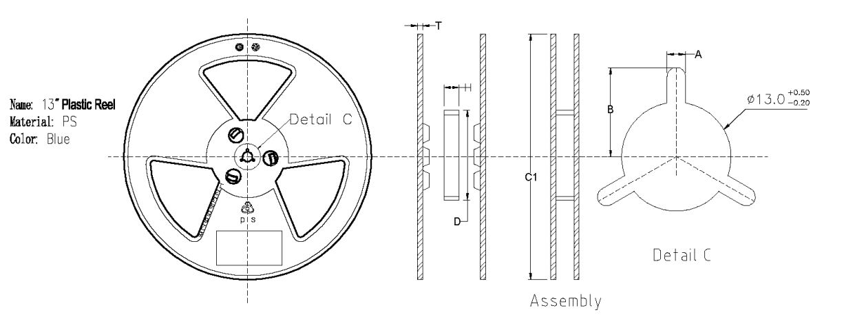
H+/-0.5 |
C1+/-1.0 |
A+/-0.2 |
C+0.5 -0.2 |
T+/-0.3 |
B+/-0.2 |
D+/-2.0 |
|---|---|---|---|---|---|---|
44.5 |
ø330 |
2.2 |
13 |
2.2 |
10.75 |
99.5 |
All dimensions are in mm.
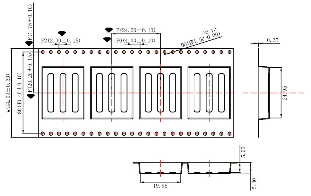
Sprocket hole pitch cumulative tolerance: +/-0.2mm.
Carrier camber not to exceed 1mm in 250mm.
All dimensions meet EIA-481-C requirements.
Thickness: 0.35mm +/- 0.05mm.
Packing length per reel: 12.6 meters.
Component load per reel: 500 pieces.
Agency Certifications
United States (FCC)
The Model SM220 modules comply with Part 15 of the FCC rules and regulations. Compliance with the labeling requirements, FCC notices, and antenna usage guidelines is required. In order to comply with FCC Certification requirements, the Original Equipment Manufacturer (OEM) must fulfill the following requirements.
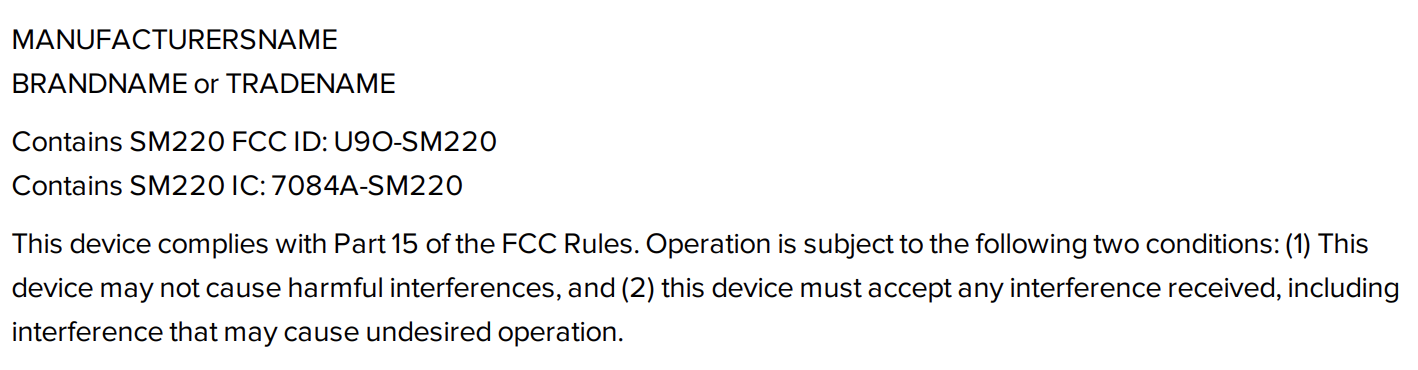
The system integrator must place an exterior label on the outside of the final product housing the SM220 Modules. FCC Label below shows the contents that must be included on this label.
SM220 Modules may only be used with the antenna that has been tested and approved for use with the module. Please refer to the antenna table provided in this section.
OEM Labeling Requirements
Attention
The OEM must make sure that FCC labeling requirements are met. This includes a clearly visible exterior label on the outside of the final product housing that displays the contents shown in FCC Label below.
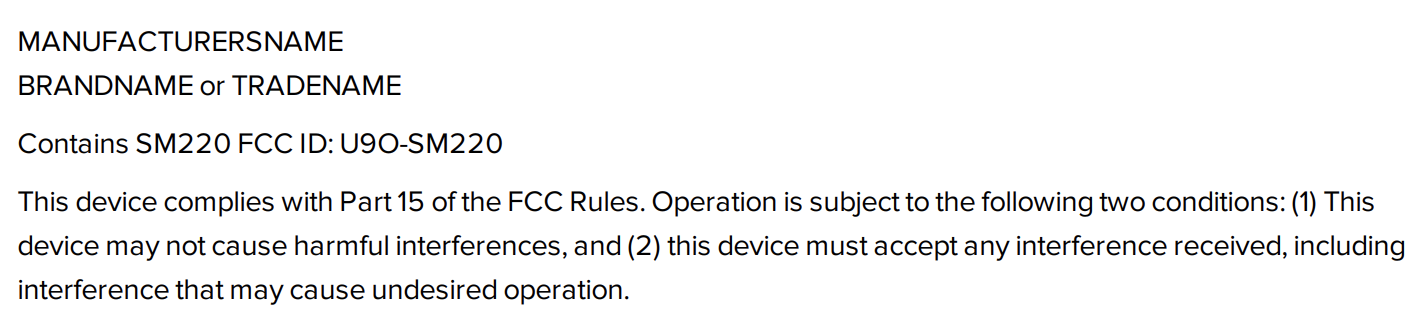
FCC Label
FCC Notices
Warning
The SM220 modules have been tested by the FCC for use with other products without further certification (as per FCC Section 2.1091). Changes or modifications to this device not expressly approved by Synapse Wireless Inc. could void the user’s authority to operate the equipment.
Attention
OEM’s must certify final end product to comply with unintentional radiators (FCC Sections 15.107 and 15.109) before declaring compliance of their final product to Part 15 of the FCC Rules.
Attention
The SM220 modules have been certified for remote and base radio applications. If the module will be used for portable applications as defined by the FCC, the device must undergo SAR testing.
Note
This equipment has been tested and found to comply with the limits for a Class B digital device, pursuant to Part 15 of the FCC Rules. These limits are designed to provide reasonable protection against harmful interference in a residential installation. This equipment generates, uses, and can radiate radio frequency energy, and if not installed and used in accordance with the instructions, may cause harmful interference to radio communications. However, there is no guarantee that interference will not occur in a particular installation.
If this equipment does cause harmful interference to radio or television reception, which can be determined by turning the equipment off and on, the user is encouraged to try to correct the interference by one or more of the following measures:
Reorient or relocate the receiving antenna.
Increase the separation between the equipment and receiver.
Connect the equipment into an outlet on a circuit different from that to which the receiver is connected.
Consult the dealer or an experienced radio/TV technician for help.
FCC Approved Antennas
The SM220 modules are FCC-approved for fixed base station, mobile, and portable applications.
Attention
To reduce potential radio interference to other users, the antenna type and its gain should be chosen so that the equivalent isotropically radiated power (EIRP) is not more than that permitted for successful communication. This module has been designed to operate with the antennas listed in SM220 Approved FCC Antennas above. The required antenna impedance is 50 ohms.
SM220 Approved FCC Antennas
Part Number |
Type |
Gain |
Application |
Min. Separation |
|---|---|---|---|---|
Compact F Antenna |
PC Board Trace Antenna |
0.0 dBi |
Fixed/Mobile |
20 cm. |
SM220 Approved FCC Antennas
Part Number |
Type |
Gain |
Application |
Min. Separation |
|---|---|---|---|---|
Pulse W1027 |
Dipole (quarter-wave RPSMA) |
3.2 dBi |
Fixed/Mobile |
20 cm. |
HyperLink HG2405RD-RSP |
Dipole (quarter-wave RPSMA) |
5.5 dBi |
Fixed/Mobile |
20 cm. |
ANT-OSC-8.0-1 |
Whip (RPSMA) |
8 dBi |
Fixed/Mobile |
20 cm. |
ANT-2.4-CW-RAH-RPS |
Helical Whip (quarter-wave RPSMA) |
1.6 dBi |
Fixed/Mobile |
20 cm. |
ANT-2.4-CW-RH-RPS |
Helical Whip (quarter-wave RPSMA) |
-0.9 dBi |
Fixed/Mobile |
20 cm. |
For more information on approved antennas, please consult the manufacturer’s website.
Warning
RF Exposure: This equipment complies with FCC radiation exposure limits set forth for an uncontrolled environment. This equipment should be installed and operated with minimum distance 20 cm between the radiator and your body. This transmitter must not be co-located or operating in conjunction with any other antenna or transmitter.
Attention
The preceding statement must be included as a CAUTION statement in OEM product manuals in order to alert users of FCC RF exposure compliance.
Note
Antenna and transmitters may be co-located or operated in conjunction with this device only if the transmitters do not simultaneously transmit. Otherwise, additional regulatory requirements will apply.
Canada (IC)
This device complies with Industry Canada license-exempt RSS standard(s). Operation is subject to the following two conditions: (1) this device may not cause interference, and (2) this device must accept any interference, including interference that may cause undesired operation of the device.
Le présent appareil est conforme aux CNR d’Industrie Canada applicables aux appareils radio exempts de licence. L’exploitation est autorisée aux deux conditions suivantes : (1) l’appareil ne doit pas produire de brouillage, et (2) l’utilisateur de l’appareil doit accepter tout brouillage radioélectrique subi, même si le brouillage est susceptible d’en compromettre le fonctionnement.
Under Industry Canada regulations, this radio transmitter may only operate using an antenna of a type and maximum (or lesser) gain approved for the transmitter by Industry Canada. To reduce potential radio interference to other users, the antenna type and its gain should be so chosen that the equivalent isotropically radiated power (EIRP) is not more than that necessary for successful communication.
Conformément à la réglementation d’Industrie Canada, le présent émetteur radio peut fonctionner avec une antenne d’un type et d’un gain maximal (ou inférieur) approuvé pour l’émetteur par Industrie Canada. Dans le but de réduire les risques de brouillage radioélectrique à l’intention des autres utilisateurs, il faut choisir le type d’antenne et son gain de sorte que la puissance isotrope rayonnée équivalente (p.i.r.e.) ne dépasse pas l’intensité nécessaire à l’établissement d’une communication satisfaisante.
This radio transmitter Model: SM220, IC: 7084A-SM220 has been approved by Industry Canada to operate with the antenna types listed below with the maximum permissible gain and required antenna impedance for each antenna type indicated. Antenna types not included in this list, having a gain greater than the maximum gain indicated for that type, are strictly prohibited for use with this device.
Le présent émetteur radio Model : SM220, IC : 7084A-SM220 a été approuvé par Industrie Canada pour fonctionner avec les types d’antenne énumérés ci-dessous et ayant un gain admissible maximal et l’impédance requise pour chaque type d’antenne. Les types d’antenne non inclus dans cette liste, ou dont le gain est supérieur au gain maximal indiqué, sont strictement interdits pour l’exploitation de l’émetteur.
In order to comply with FCC/ISED RF Exposure requirements, this device must be installed to provide at least 20 cm separation from the human body at all times.
Afin de se conformer aux exigences d’exposition RF FCC / ISED, cet appareil doit être installé pour fournir au moins 20 cm de séparation du corps humain en tout temps.
SM220 Approved IC Antennas
Part Number |
Type |
Gain |
Application |
Min. Separation |
|---|---|---|---|---|
Compact F Antenna |
PC Board Trace Antenna |
0.0 dBi |
Fixed/Mobile |
20 cm. |
SM220 Approved IC Antennas
Part Number |
Type |
Gain |
Application |
Min. Separation |
|---|---|---|---|---|
Pulse W1027 |
Dipole (quarter-wave RPSMA) |
3.2 dBi |
Fixed/Mobile |
20 cm. |
HyperLink HG2405RD-RSP |
Dipole (quarter-wave RPSMA) |
5.5 dBi |
Fixed/Mobile |
20 cm. |
ANT-OSC-8.0-1 |
Whip (RPSMA) |
8 dBi |
Fixed/Mobile |
20 cm. |
ANT-2.4-CW-RAH-RPS |
Helical Whip (quarter-wave RPSMA) |
1.6 dBi |
Fixed/Mobile |
20 cm. |
ANT-2.4-CW-RH-RPS |
Helical Whip (quarter-wave RPSMA) |
-0.9 dBi |
Fixed/Mobile |
20 cm. |
IC OEM Labeling Requirements
Labeling requirements for Industry Canada are similar to those of the FCC. A clearly visible label on the outside of the final product housing must display the contents shown in IC Label below.
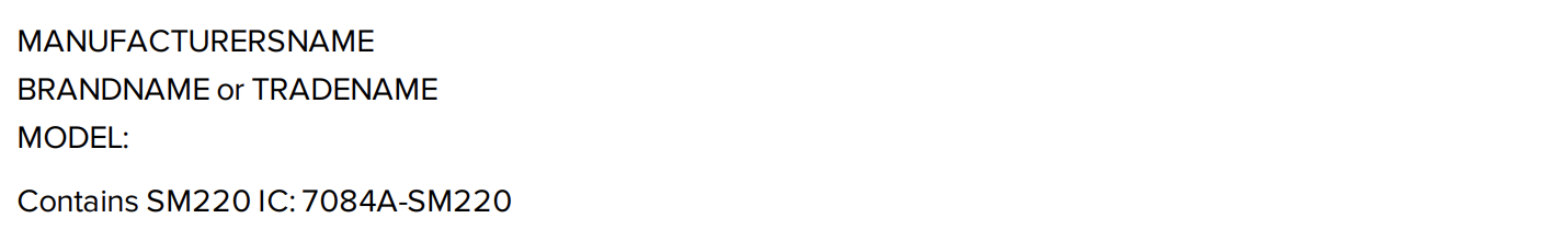
IC Label
Note
The OEM can choose to implement a single label combined for both FCC and IC labeling requirements. If a combined single label is chosen, there must be a clearly visible label on the outside of the final product housing displaying the contents shown in Combined FCC and IC Label below.
Combined FCC and IC Label
ESD Warnings
During your manufacturing or assembly process, it is critical to have good ESD controls in place when handling the device or connecting an external antenna to the u.FL connector.
During field installation process, Synapse recommends the following practices when connecting an antenna or cable to the RP-SMA bulkhead:
NEEDED MATERIALS * 50 OHM Terminator plug RP-SMA: Part Number 132360RP from Amphenol
ATTACHING THE TERMINATOR TO THE BULKHEAD Make sure the power is off. Attach the 50 OHM Terminator to the RP-SMA bulkhead hand tight. Keep the 50 OHM Terminator on the bulkhead at all times, until the antenna replaces the 50 OHM Terminator. When installing the device, the technician must be grounded with a proper ground strap.
ATTACHING THE ANTENNA When it is time to attach the antenna, touch a grounded surface, remove the 50 OHM Terminator and screw on the antenna tightly. Tighten a 1/4 turn with a pair of needle nose pliers. Do not overtighten or the RF pin in the bulkhead will crack, creating poor RF link quality.